
Selecting a Battery Management System for Safe, Scalable Energy Storage Projects
A Battery Management System becomes a procurement issue long before a battery cabinet is installed. The pressure usually appears when a project team is comparing storage suppliers whose datasheets all claim protection, monitoring, and communication capability, yet the site requirements are not identical. A system may need to follow a power conversion system command, report to an energy management platform, operate in hot or cold weather, and isolate a fault without taking healthy equipment offline unnecessarily.
The core selection rule is straightforward: choose a Battery Management System that matches the project’s battery architecture, protection strategy, operating environment, and control interfaces—not one that merely lists a long set of functions. For procurement teams, the best decision is usually made by turning site needs into verifiable requirements: what the BMS must measure, what it may control, how it must communicate, what happens during a fault, and who can access the resulting data over the system lifecycle.
Start with the operating scenario, not the feature list
“BMS included” is not a meaningful evaluation result on its own. The same label can describe a board that monitors individual cells in a small battery pack or a layered control system coordinating racks, clusters, fire protection signals, HVAC status, contactors, and external energy controls. The necessary depth depends on the installation.
For a high-capacity storage project, procurement should first clarify the physical and operational boundaries. Is the system a standalone commercial storage unit, part of a containerized battery energy storage system, or integrated into a larger grid-connected plant? Will it cycle daily for peak shifting, remain on standby for backup, or support irregular renewable generation? These conditions affect the required data refresh rate, balancing approach, thermal coordination, state estimation accuracy, and fault-response logic.
A useful early discussion involves four engineering questions:
- What is the smallest battery unit that must be monitored: cell, module, pack, rack, or cluster?
- Which component has final authority to stop charging or discharging during a hazardous condition?
- Which external systems need information or control access, such as PCS, EMS, SCADA, HVAC, or site fire systems?
- What site conditions could reduce performance or change protection behavior, including temperature, altitude, humidity, dust, and restricted maintenance access?
These questions prevent a frequent mismatch: buying a system with sufficient nominal capacity but inadequate control granularity. A BMS that only reports aggregate voltage may be unsuitable where cell-level deviation must be identified early. Conversely, specifying a highly customized control stack for a simple, isolated application can add integration effort without improving the real operating outcome.
Evaluate protection as a coordinated response, not a list of alarms
Voltage, current, and temperature protection are baseline requirements. The procurement decision lies in understanding how the BMS reacts when a measurement crosses a threshold. An alarm that appears in a dashboard is useful, but it is not equivalent to an enforced protection action. Ask suppliers to describe the sequence from detection through shutdown, including delays, recovery conditions, event recording, and the interfaces affected.
For example, an over-temperature event may require more than opening a contactor. The BMS may need to derate charge or discharge power before the threshold is reached, command cooling equipment, inform the PCS to reduce current, generate an alarm for the supervisory system, and then isolate the affected section if conditions continue to worsen. The required sequence depends on the overall system design, but it should be defined rather than assumed.
Protection points that need explicit answers
During technical clarification, request specific information for over-voltage, under-voltage, over-current, short-circuit, insulation-related conditions where applicable, over-temperature, under-temperature, communication loss, sensor failure, and abnormal cell deviation. For each condition, confirm the following:
- Detection level: Is the condition detected at cell, module, pack, cluster, or system level?
- Action level: Does the BMS alarm, limit power, open contactors, request PCS shutdown, or trigger a wider emergency sequence?
- Priority logic: What occurs when multiple events appear at the same time?
- Reset conditions: Can the system restart automatically, only after values return to range, or only after an authorized manual reset?
- Traceability: Are time-stamped fault records retained and exportable for maintenance review?
Threshold values alone do not provide this picture. They also need context: sensor location, filtering, delay time, the permitted operating current at different temperatures, and whether limits can be adjusted. Adjustable parameters can be useful, but unrestricted field changes can create safety and warranty risk. A controlled access method, parameter version management, and documented approval process are more valuable than broad editability.
Do not treat the fire-protection interface as separate from BMS procurement. The BMS may provide the early electrical and thermal signals that support an emergency response, while the fire system may return status signals that affect battery operation. The signal relationship, fail-safe state, and alarm ownership should be clear in the interface documentation.
Check measurement quality before relying on SOC and SOH claims
State of charge is often used as if it were a directly measured value. In practice, it is an estimate produced from voltage, current, temperature, battery characteristics, and calculation logic. The same applies to state of health. These values influence dispatch decisions, usable energy estimates, maintenance planning, and contractual operating expectations, so procurement teams should ask how they are generated and maintained rather than accepting a dashboard display as proof of accuracy.
Relevant questions include current sensor range and accuracy, voltage sampling resolution, temperature sensor placement, calibration provisions, data sampling frequency, and behavior after a power interruption. A BMS should also identify missing, implausible, or drifting sensor data instead of silently using a bad signal to calculate battery status.
Cell consistency matters particularly in LFP systems because voltage can remain relatively flat over a substantial portion of the operating range. The BMS needs a credible way to observe divergence through charging, discharging, rest periods, and temperature changes. Procurement should determine whether the supplier provides cell voltage distribution data, maximum-to-minimum cell deviation, temperature spread, and historical trend records. These are more actionable than a single averaged voltage value.
Balancing should fit the duty cycle and service approach
Passive balancing dissipates energy from higher-voltage cells to support pack consistency. It is a practical and widely used method, but its suitability should be judged against the system’s duty cycle, cell matching, expected imbalance behavior, and available maintenance windows. A specification that simply states “balancing included” leaves too much unresolved.
Ask when balancing operates: during charging, after full charge, at rest, or under defined voltage and temperature conditions. Also ask what data indicates that balancing is no longer sufficient and whether the BMS identifies a persistently weak cell or module. In high-utilization installations, waiting for a convenient idle period may not suit the operating schedule. The supplier should explain how the stated balancing method relates to the intended use profile.
Communication compatibility often determines whether commissioning stays on schedule
Many BMS selection problems are discovered during integration, not during purchasing. The battery can be electrically sound while the project is delayed because the PCS expects one set of command and status objects, the EMS uses another naming convention, and the BMS interface document leaves key states undefined.
Before placing an order, obtain the communication protocol documentation and compare it with the required system architecture. LAN, CAN, and RS485 may all be available, but the physical port is only the starting point. The important questions concern message definitions, data ownership, update timing, command priority, fault codes, handshake states, and behavior when communications are lost.
A practical procurement requirement is to ask for a point list and protocol map before final technical approval. It should show not only available data but also which values are mandatory, optional, calculated, writable, or fixed. This helps distinguish an interface that can physically connect from one that supports the required operating logic.
Match BMS architecture to scale and maintainability
Scalability is not only a capacity question. Adding battery cabinets or clusters changes the number of monitored units, communication paths, contactor coordination points, and potential fault boundaries. A system that works cleanly at one rack may become difficult to diagnose when expanded unless the hierarchy is clearly designed.
For larger installations, review whether the architecture separates cell monitoring, pack control, cluster control, and higher-level supervisory functions. The exact naming differs by supplier, but the purchasing team should understand where decisions are made. For instance, a local unit may detect cell temperature, while a master controller aggregates availability and communicates a permissible power limit to the PCS. This arrangement can be appropriate, provided that loss of one communication link has defined consequences.
Maintenance access deserves similar attention. Technicians need a practical way to identify the affected location, retrieve event history, verify sensor status, and confirm replacement compatibility. Fault visibility should not stop at a generic “battery alarm.” When multiple racks are installed, the system should identify the relevant rack, pack, module, or other serviceable level supported by its architecture.
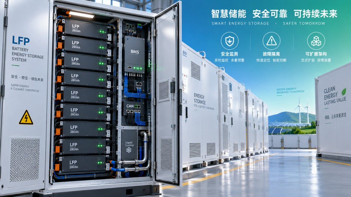
Consider a unit designed for high-capacity energy storage such as 372kWh. Its listed passive balancing, liquid cooling, LAN/CAN/RS485 communication options, and LFP battery configuration illustrate why BMS evaluation must extend across battery, thermal, protection, and controls interfaces. In this type of system, buyers should verify how cooling status and battery temperature limits interact, how cluster-level signals are exposed externally, and how the BMS supports safe operation across the specified voltage range.
Environmental conditions change the real specification
A BMS cannot make unsuitable hardware immune to its surroundings, but it must correctly manage the battery within those surroundings. Procurement specifications should therefore connect environmental limits to operating logic. High ambient temperature may require cooling control and power derating; low temperature may restrict charging; condensation risk may affect insulation and sensor reliability; altitude can influence thermal performance and equipment selection.
Ask suppliers to identify the operating temperature range, humidity limitations, enclosure protection level, noise conditions, and altitude limit together with any associated derating rules. A broad temperature range is incomplete without an explanation of what charge and discharge power remains available at different points within that range. The BMS should receive or control the information needed to apply these limits.
Thermal design is particularly relevant for tightly packed systems. Liquid cooling can provide more controlled heat removal than passive air circulation in demanding applications, but the selection review should include coolant monitoring, pump or flow status feedback, temperature sensor redundancy where provided, and the action taken when cooling performance is reduced. The BMS does not replace the thermal system; it must coordinate with it effectively.
Use lifecycle evidence in the supplier comparison
Lowest initial price can become misleading when commissioning support, documentation quality, spare-part continuity, and diagnostic access are weak. A BMS is expected to remain useful over years of operation, including periods when firmware updates, component replacement, capacity expansion, or changing grid-control requirements may occur.
Request lifecycle information that can be reviewed contractually: firmware version policy, update method, rollback provisions, compatibility management after replacement, event-log retention, available service tools, and responsibilities for interface changes. It is also reasonable to ask how a battery module replacement is recognized by the BMS and whether recommissioning or parameter synchronization is required.
Data availability has ongoing value. The system should provide the records needed to investigate recurring alarms, unequal temperature patterns, abnormal cell voltage spread, contactor behavior, and reduced available power. Procurement should define who owns the operating data, how it can be exported, and whether access remains possible without dependence on a proprietary cloud platform.
A decision sequence that exposes weak proposals early
- Define the application duty cycle, required usable energy, operating environment, and external control architecture.
- Map the battery hierarchy and identify the level at which monitoring, isolation, and reporting are required.
- Set protection expectations by event type, including alarms, derating, shutdown authority, reset conditions, and records.
- Review measurement and estimation methods for voltage, current, temperature, SOC, SOH, and cell consistency.
- Compare communication documents with the actual PCS, EMS, and SCADA requirements before equipment delivery.
- Evaluate thermal coordination, enclosure limits, and derating behavior against the installation site.
- Confirm commissioning deliverables, service access, firmware governance, and replacement procedures.
The strongest proposal is not necessarily the one with the most software screens or the longest alarm list. It is the one that provides clear limits, usable data, defined fault behavior, and an interface structure that the rest of the storage project can reliably use. That is the standard by which a Battery Management System should be selected for a safe, scalable installation.