
Forklift Battery Safety Standards Buyers Should Verify Before Purchasing
Forklift battery safety should be evaluated as a system of controls rather than a single battery attribute. A battery chemistry label, a stated runtime, or a charger rating does not reveal whether the complete power system can detect abnormal conditions, prevent unsafe operation, and remain protected in a busy warehouse. The relevant questions concern the interaction among cells, battery management electronics, high-current connections, enclosure construction, charging equipment, and the truck itself.
A suitable battery must also match the duty cycle and physical environment. Cold-storage work, multi-shift loading bays, washdown areas, uneven outdoor yards, and high-throughput indoor routes impose different stresses. A system that performs safely in a dry, temperature-controlled facility can require different sealing, thermal control, cable protection, or charge restrictions when exposed to moisture, dust, vibration, and rapid charging.
Safety evidence must apply to the delivered configuration
Certification claims require careful reading. A document may cover individual cells, a battery module, a charger, or a complete battery pack, and these are not interchangeable. A safe cell does not by itself confirm the protection of the assembled pack, its contactors, harnesses, fuse coordination, software limits, or vehicle interface. Similarly, a report for one voltage and capacity configuration cannot automatically be transferred to a different enclosure, series connection, or cooling arrangement.
Request documentation that identifies the exact battery model, electrical rating, enclosure version, charger compatibility, and intended application. The scope should distinguish transport-related testing from tests covering electrical safety, environmental exposure, electromagnetic behavior, and functional controls. Where local workplace rules or vehicle requirements apply, the evidence should be reviewed against those requirements rather than treated as a generic approval.
Document control matters as much as document presence. Revision dates, serial-number traceability, test conditions, and declared limitations should be clear. An approval that excludes the installed charger, assumes indoor use, or relies on a particular mounting orientation can leave an important gap if the proposed installation differs.
Thermal protection needs a defined response chain
Lithium battery safety depends heavily on recognizing and managing temperature changes before they reach a damaging level. Temperature sensing should cover locations that are meaningful for the battery design, such as representative cell areas, power terminals, and zones near high-current components. A single sensor in a favorable location can mask a localized connection problem or uneven heating between modules.
The specification should state what happens when temperature rises, falls below the permitted charging range, changes too rapidly, or differs materially between monitored zones. Useful responses are staged: a warning visible to the vehicle or charging interface, controlled current reduction, charge inhibition where appropriate, and isolation when a defined fault threshold is reached. The thresholds need not be published in full to establish confidence, but the response logic and reset conditions should be explainable.
Fast opportunity charging makes this review more important. Higher current can be acceptable within a validated design, yet it increases the importance of cable sizing, connector condition, heat dissipation, and charge-control communication. Temperature behavior during charging is distinct from temperature behavior during discharge. A battery that can power a truck in a cold facility may still need charging to remain blocked until its cells are within the approved range.
Liquid cooling, forced-air cooling, and passive thermal designs should be judged against the actual thermal load and service environment. Liquid cooling adds heat-transfer capability but also introduces hose, fitting, coolant, leakage-detection, and maintenance considerations. Passive systems have fewer auxiliary components but require sufficient thermal margin for the expected current profile. Cooling hardware alone is not proof of thermal safety; sensing, alarms, shutdown behavior, and fault diagnosis remain necessary.
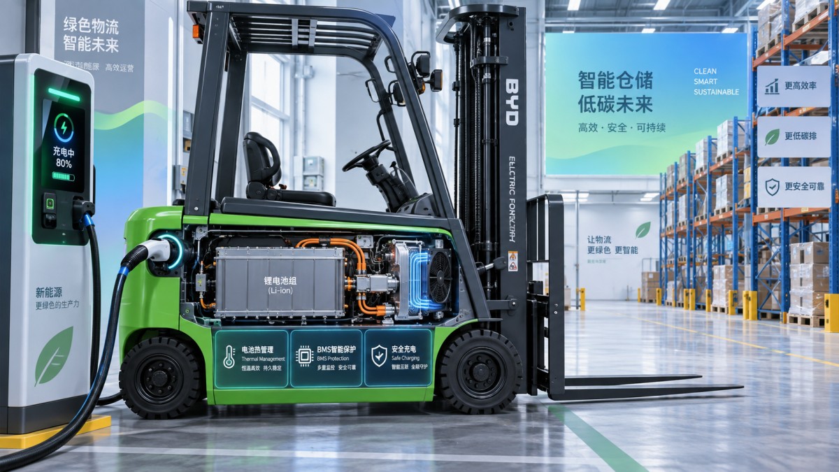
Battery management should control faults, not merely display data
The battery management system, or BMS, is the decision layer between the cells and the vehicle. It should monitor cell voltage, pack voltage, current, temperature, insulation-related conditions where applicable, and the status of critical switching components. More importantly, it must act on that information in a controlled and repeatable way.
Ask how the BMS handles overcharge, over-discharge, overcurrent, short-circuit indications, cell-voltage imbalance, sensor failure, communication loss, and contactor welding. These events have different consequences. A low state of charge may justify a controlled reduction in available power, while a detected short-circuit condition requires a much faster protective response. Treating all faults as a generic “alarm” obscures whether the system can place itself in a safe state.
Cell balancing is often described without enough context. Passive balancing can be appropriate when the pack design, charge strategy, and maintenance approach keep cell deviation within controlled limits. It dissipates energy from higher-voltage cells and is generally most effective under specified operating conditions. Its presence should not be interpreted as a remedy for persistent imbalance caused by a weak cell, damaged connection, unsuitable charger behavior, or repeated operation outside the intended state-of-charge window.
The BMS should retain useful fault records. A service technician needs enough information to distinguish a genuine cell issue from a loose connector, intermittent temperature sensor, vehicle-side voltage drop, or charger communication error. Event records with time, relevant measurements, and fault state support diagnosis and reduce the risk of repeatedly resetting a condition whose cause has not been addressed.
Communication is also a safety function. The battery, truck controller, display, and charger may exchange permitted current limits, state of charge, fault status, and authorization signals through CAN, LAN, RS485, or another defined interface. Verify that loss of communication results in a known protective behavior. A truck should not continue drawing unrestricted power simply because its control system no longer receives battery limits, and a charger should not proceed with an undefined charging profile after a communication fault.
High-voltage and high-current protection must be examined together
Forklift packs operate at lower voltage than utility-scale energy storage equipment, but their currents can still be substantial during lifting, acceleration, or hydraulic demand. The safety review should therefore cover both shock protection and thermal stress at connections. Protective devices must be coordinated so that a fault is interrupted without allowing conductors, terminals, or connectors to exceed their design limits.
Fuses, contactors, pre-charge circuits, service disconnects, and emergency isolation devices each have a different role. A fuse is not a substitute for a contactor-controlled shutdown, while a contactor does not remove the need for properly selected overcurrent protection. The pre-charge circuit deserves attention because it limits inrush current when connecting a battery to vehicle electronics with capacitive loads. Failure in this area can cause contactor damage, welded contacts, or repeated startup faults that are incorrectly blamed on the battery.
Insulation performance should be stated with a test method, voltage, duration, and acceptance criterion. A high insulation value measured in a dry factory test is useful, but installation conditions can change the result. Condensation, contaminated surfaces, damaged cable glands, trapped water, and abrasion at a cable exit may progressively reduce insulation resistance. The enclosure, harness routing, and maintenance access must protect against those mechanisms.
Industrial battery documentation sometimes includes values such as leakage-current limits and insulation-resistance thresholds. For example, the technical data associated with 5MW-II identifies both a leakage-current test condition and an insulation measurement criterion. Those figures are relevant as an example of how electrical safety claims should be expressed: a number without the applied test duration, voltage, system boundary, and acceptance condition is difficult to evaluate. The actual requirements for a forklift battery must be established for its own voltage architecture and intended installation.
Enclosure protection is shaped by the work area
Battery enclosure design should be reviewed from the outside inward. The housing must resist impact and vibration while maintaining protection at doors, seals, vents, cable entries, handles, and mounting points. A robust-looking metal case can still be vulnerable if its cable gland loosens under vibration or if its service cover can be refitted without restoring the original seal.
An ingress-protection rating is meaningful only when tied to the installed condition. Consider whether the truck works near wet floors, receives washdown, crosses exterior loading areas, or encounters airborne dust. Water exposure is not uniform: splash from below, direct spray at a connector, and condensation inside an enclosure are different situations. The stated protection level should therefore be considered alongside connector orientation, drainage paths, pressure equalization features, and restrictions on cleaning methods.
Mechanical fit is part of forklift battery safety. Battery weight, center of gravity, restraint points, clearance to moving parts, and cable bend radius all affect service reliability. A battery that shifts in its compartment can damage connectors or compromise vehicle stability. Retrofitting also needs a review of tray geometry, retention hardware, interlock arrangements, and any changes to counterbalance weight. Electrical compatibility without mechanical compatibility is incomplete.
Charging equipment has to be treated as part of the battery system
A charger should be approved for the battery chemistry, nominal voltage, permitted voltage range, current capability, and communication method. Plug compatibility alone is insufficient. An incorrect charging curve can create chronic overvoltage, incomplete charge, unnecessary heat, or repeated BMS shutdowns. The charger should follow battery-imposed limits, particularly when cell temperature, state of charge, or fault status changes during a charge session.
Charging locations need adequate electrical infrastructure and practical protection against damaged leads, connector contamination, and vehicle impact. Cable reels, strain relief, parking positions for connectors, and clear access for emergency isolation are operational details with direct safety consequences. A connector lying on a wet floor or repeatedly pulled by its cable can create a fault that no battery specification can compensate for.
Clarify behavior after a power interruption. Some chargers resume automatically, while others require a new authorization sequence. Neither approach is universally preferable; the safe choice depends on whether the battery and charger re-establish communication, reassess conditions, and prevent uncontrolled restart after a fault. The same review applies to brief communication interruptions and emergency-stop activation.
Installation and service boundaries should be explicit
Safe equipment can become unsafe through an uncontrolled installation. The supplied instructions should identify permitted mounting positions, torque requirements for power connections, cable-routing rules, grounding provisions, sealing requirements, and the inspection points needed after commissioning. If the installation uses adapters, modified trays, extension leads, or nonstandard connectors, responsibility for validating the altered assembly should be clear.
Maintenance arrangements should cover inspection intervals and fault escalation without encouraging unnecessary opening of a high-energy enclosure. Relevant signs include recurring charge interruptions, unusual connector heating, damaged cable insulation, fluid traces near cooled equipment, repeated imbalance warnings, corrosion around terminals, and unexplained reduction in available power. Resetting a fault may restore operation temporarily, but it should not replace investigation when the same condition returns.
End-of-life handling and transport preparation deserve early attention. A battery removed after impact, overheating, water ingress, or an unresolved fault may require different containment and transport controls from a routine replacement unit. The documentation should define the information needed to identify battery status and any restrictions on moving or storing a suspect pack.
A defensible safety decision comes from matching documented protective functions to the real vehicle, charger, facility conditions, and service process. The strongest evidence is specific: it shows what was tested, which configuration was covered, what fault response is expected, and where the operating limits begin. That level of detail prevents safety from being reduced to a label on the battery enclosure.