
Forklift Battery Charging Time: What Determines Fast and Safe Charging Cycles?
Forklift battery charging time should be evaluated as a complete operating cycle: the energy removed during work, the power the battery can accept at its present state and temperature, the charger’s controlled output, and the time required for safe balancing and cooling. A charger with a high nameplate rating does not automatically produce a shorter usable turnaround. If the battery management system reduces current near full charge, or if the pack arrives hot from a demanding shift, the final portion of the cycle can dominate the schedule.
For electric forklifts, a realistic charging plan starts with the required energy window rather than a generic statement such as “full charge in several hours.” The relevant question is whether the available charging windows restore enough energy for the next duty period without forcing repeated high-stress charging events. That distinction affects truck availability, electrical infrastructure sizing, battery replacement intervals, and the operating discipline needed around charging stations.
Start with energy removed, not the battery label
Battery capacity is expressed in kilowatt-hours, while charger output is expressed in kilowatts. At a simplified level, charging time equals energy that must be returned divided by the average power delivered. The word average matters. A battery does not receive maximum charger power throughout the entire cycle, and energy losses mean that more energy enters from the grid than was delivered to traction work.
A 100 kWh pack discharged from 90% state of charge to 30% has used roughly 60 kWh of stored energy. A charger rated at 30 kW would suggest a two-hour calculation before losses and current taper. That calculation is useful as a first screen, but it is not an operating promise. The charger may be limited by the battery’s accepted current, the site supply, programmed charge profile, connector temperature, or a power-sharing arrangement with other chargers.
Depth of discharge changes the result in two ways. A deeper discharge requires more energy to be replenished, and it may leave the battery at a temperature or voltage condition that changes its permitted charging current. Repeatedly taking a pack close to its low state-of-charge limit can also leave little schedule margin when work intensity rises unexpectedly. Conversely, shallow opportunity charges can maintain availability, but only when the chemistry, battery controls, and duty cycle support that pattern.
Battery chemistry sets the charging envelope
Lead-acid and lithium-ion forklift batteries should not be assessed with the same charging assumptions. Lead-acid batteries normally require a structured multi-stage charge, including an absorption phase in which current falls as voltage rises. They also need time for gassing control, electrolyte behavior, and, in many operations, cooling before return to service. A fast charger can shorten the bulk stage, but it cannot remove the electrochemical limits that protect the battery.
Lithium-ion batteries generally accept higher charge power over a wider portion of their state-of-charge range and do not require the same equalization routine. Their charging time can therefore be more flexible for multi-shift operation. Yet lithium-ion charging is still governed by cell temperature, cell voltage, charge-rate limits, and the battery management system. A pack that reaches its upper voltage threshold will transition from constant-current charging toward a reduced-current phase. This is why the final percentage of charge is often slower than the middle of the cycle.
Chemistry alone is not enough. Cell format, electrode design, pack architecture, cooling arrangement, and BMS calibration determine the allowed charge curve. Two lithium-ion packs with similar kWh ratings can have materially different turnaround behavior. A specification that states only nominal capacity cannot establish whether a pack can support high-power opportunity charging throughout a shift.
Rated charger power and accepted power are different values
The charger rating is the maximum it can supply under specified conditions. Accepted power is what the battery and connected system permit at a particular moment. The lower of those values controls actual charging speed.
A charge-rate value expressed as C-rate provides a more useful comparison than charger kilowatts alone. A 0.5C charge rate means a battery is charged at a current corresponding, in an idealized sense, to half of its rated capacity per hour. It does not mean the pack will be fully charged in exactly two hours, because charging losses and taper remain. Still, C-rate links the charger to the battery’s size and makes it easier to distinguish between a high-power charger used on a small pack and the same charger used on a much larger pack.
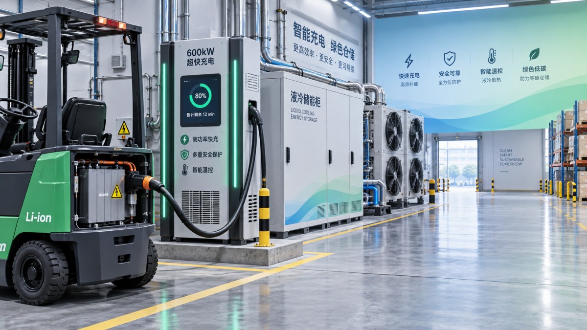
Stationary energy storage may be part of the charging architecture where site power is limited or demand peaks must be managed. For example, a liquid-cooled LFP storage unit such as 233kWh is relevant only when its usable power, inverter rating, control response, and recharge window are matched to the forklift charging profile. Stored energy capacity by itself does not demonstrate that it can support a specific number of concurrent fast charges.
Temperature can change a planned charging window
Battery temperature affects internal resistance and the electrochemical rate at which cells can safely accept charge. A battery returning from heavy lifting, long travel distances, ramp work, or repeated acceleration can arrive at the charger warmer than expected. If the pack temperature is above its preferred charging range, the BMS may reduce current until cooling brings conditions back within limits. The apparent problem is often described as a slow charger even though the charger is responding correctly.
Cold batteries create a different constraint. Charging lithium-ion cells at low temperatures may require substantial current reduction or preheating, depending on cell design and control settings. A fleet that works outdoors, moves between cold storage and loading areas, or remains idle in an unconditioned building should assess the temperature of the battery at plug-in, not merely the ambient temperature at the charging station.
Thermal management also affects charging consistency over time. Liquid cooling can remove heat more evenly from high-energy battery assemblies than passive arrangements in demanding use cases, but the complete loop matters: coolant temperature, pump operation, heat-exchanger condition, sensor placement, and control logic all influence the result. A cooling system that is adequate during ordinary work may require different settings during clustered fast-charging periods.
Charging strategy must match the shift pattern
There are three broad approaches, each with different scheduling implications. Conventional overnight charging restores a large portion of battery energy during a long idle period. It simplifies scheduling when trucks have predictable single-shift use, but it requires enough time for the full controlled cycle and any required cooling period.
Opportunity charging adds energy during planned breaks, staging intervals, or other natural pauses. It can reduce the need for battery changes and keep a truck available across multiple shifts. Its success depends on repeatable breaks, adequate charger access, and a battery designed for the intended charge rate. Short stops are not automatically useful if plug-in procedures consume much of the available time or if chargers are routinely occupied.
Battery swapping separates charging time from vehicle downtime by using a spare battery inventory. It can work where duty cycles are intense and battery packs are designed for safe handling, but the analysis must include exchange equipment, battery staging space, spare-pack charging, weight handling, and the condition variation among packs. A fast charge system and a swap system should be compared against the same availability target, not against their most favorable individual metric.
The most reliable plan often uses state-of-charge thresholds rather than a fixed clock-only rule. A truck that has performed light work does not need the same replenishment as one assigned to continuous heavy lifting. BMS data, truck energy consumption, and actual charge session records can reveal whether a charging schedule is restoring the expected energy or simply creating a queue at shift changes.
Where charging time estimates fail
A common error is to divide nominal battery capacity by charger rating and treat the result as the shift-planning value. That skips the starting state of charge, charge efficiency, taper, thermal derating, and charger sharing. It can understate required time substantially, especially where full charges are scheduled close to shift start.
Another error is comparing time to 80% state of charge with time to a fully usable operating state without confirming the application’s energy reserve. Eighty percent may be sufficient for a short task, yet inadequate for a full remaining shift. The reverse can also be true: insisting on 100% after every partial use can create unnecessary station congestion and keep a battery in its upper state-of-charge region longer than the operating pattern requires.
Site electrical limits are sometimes discovered after equipment selection. A charger can be technically compatible with the battery while the building feeder, transformer, panel capacity, or cable run cannot support all units at rated output. Dynamic load management can reduce this constraint, but it changes the individual charger’s real power during peak demand. Charge-cycle calculations should therefore use the managed power available during the busiest expected period.
Safe charging is a controlled connection process
Safe charging begins before energy flows. The truck should be parked in the designated location, stabilized, and disconnected from productive work. Connector faces, pins, latches, and cable insulation need to be clean and intact. A loose or damaged connection can create resistance heating, intermittent communication, and repeated charge interruptions that look like battery faults.
- Confirm that the charger and battery communicate correctly before assuming a slow session is caused by low charger output. Fault codes, requested current, pack temperature, and state of charge identify different failure paths.
- Keep charging areas clear of materials that obstruct ventilation, access, or emergency response. Cable placement should prevent pulling, crushing, and trip hazards without placing strain on the connector.
- Investigate a sudden reduction in charging speed rather than overriding protective limits. A temperature sensor issue, coolant-flow problem, aging connector, unbalanced cell group, or facility power restriction requires a different correction.
- Use the approved charge profile for the battery. Substituting a charger with an unsuitable voltage range, communication protocol, or current limit can shorten neither the schedule nor the battery’s service life.
Use measured cycle data for the final decision
The practical measure of forklift battery charging time is not a laboratory value or a single successful fast-charge event. It is the repeatable time from plug-in to the energy level required for the next assignment, measured under representative workload, temperature, and simultaneous charging conditions. Records should distinguish charger-connected time from active energy-transfer time, because queues, connection faults, cooling delays, and power sharing are operational constraints even when the battery itself is healthy.
A sound evaluation also compares delivered energy with expected truck consumption. If a pack appears to charge normally but its available run time falls, the issue may be energy use, battery condition, state-of-charge estimation, or an application mismatch rather than charging speed. Treating charging time as a system outcome keeps attention on the conditions that determine both fast turnaround and safe battery operation.